 Setting cable preferences
Set the cable preferences prior to inserting cables in the drawing. Setting the spare cable lengths and selecting a cable set ensures that all cables are placed in a similar way that works with the needs of the venue.
|
Command |
Path |
|
Cable Preferences |
Spotlight > Cables and Power Planning |
To set the cable preferences:
Select the command.
Click to show/hide the parameters.Click to show/hide the parameters.
|
Parameter |
Description |
|
General Settings |
|
|
Cable Swag (%) |
Sets the percentage of extra length used as swag (extra length to span gaps in the rigging) for non-horizontal cables |
|
Spare Data Cable/ Multi Cable/ Feeder Cable/ Jumper Cable |
Specifies the additional length added to the start and end of each type of cable so that the cable is not stressed to make a connection to the distributor |
|
Automatically curve connector cables (Distributor and Daisy Chain mode only) |
Draws cables with a curve as a visual indicator of the mode, even though the cables directly connect two electrical devices |
|
Automatically create cables when devices get connected |
Draws cables between two devices once they've been connected. To specify the cable style or otherwise edit the cable, see Editing cables. |
|
Automatically follow paths when a cable is drawn |
Draws cables along existing cable paths or truss paths, using the most efficient route to connect devices |
|
Gap between cables and cable path |
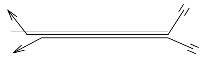
Cables that overlap on a shared cable path can be drawn at an offset, so it's easier to select the individual cables. Specify the distance that separates each cable.
Two offset cables on a shared cable path |
|
Default Parts |
|
|
Use Cable Set |
Specify the set of cables to use, or select <All> to not be limited to a set. See Managing cable parts for details about assigning a cable to a set and creating new sets. |
|
Cable Part Selection |
Defines how to create cable paths from the parts available in the set. Fewest parts: If using the fewest number of cable parts is preferred, this option allows the cable run to be longer than the specified path. For example, a single 50 ft cable is selected for a 45 ft path, instead of using two 20 ft cables and one 5 ft cable to achieve the required length. This creates fewer connection points, and therefore, fewer failure points. Best fit: If reaching the required length as closely as possible is preferred, this option selects cable parts to meet the specified cable path length as closely as possible. This option may use more parts, breaking long cable runs into multiple parts so they are easier to handle and not as heavy. |
|
Fewest parts threshold (Fewest parts only) |
Defines the maximum length that a cable can extend beyond the required length but still be selected |
|
Save as Default |
Saves the current settings as the default settings for this and future documents |
Specify the settings for cable objects.
Defining preferences for a specific area
|
Tool |
Tool set |
|
Cable Area |
Preview |
It can be very useful to set different cable preferences for different areas and even layers of the drawing. In particular, different cable sets and other default parts settings may apply to different areas of a venue. Different teams (lighting, sound, power, video, and so on) have different requirements depending on discipline and location. Different parts of the venue can require varying amounts of slack in the cables. Define the settings in an area with the Cable Area tool.
![]()
|
Mode |
Description |
|
Create from Shape
|
Converts an existing polyline, polygon, rectangle, circle, or arc to a cable area and applies the current preference settings |
|
Oval
|
Creates an oval-shaped cable area |
|
Rectangle
|
Creates a rectangular cable area |
|
Polyline
|
Defines the cable area with a polyline; select a polyline creation option |
|
Polyline creation options |
Selects the method for drawing the polyline upon which the object is based; see Creating polylines |
|
Fillet Radius
|
For Arc Vertex polyline mode, enter the fillet radius |
|
Automatic Numbering
|
Enables automatic numbering of cable areas as they are placed |
|
Numbering Preferences
|
Set the default parameters for automatic numbering of cable areas |
To define an area of cable preferences:
Click the tool. From the Tool bar, enable Automatic Numbering if desired, and specify the Numbering Preferences. See Automatic numbering preferences.
Do one of the following:
Draw a closed shape using basic tools (see Basic drawing objects). Click Create from Shape mode from the Tool bar, and click on the existing shape.
Select a drawing mode from the Tool bar, and draw the cable area shape.
From the Object Info palette, click Settings.
The Cable Area Settings dialog box opens.
Define the preferences that apply to the area; see Setting cable preferences.
Enter a Location name for paperwork. To restrict the cable area to the current layer, select Only apply to objects on this layer from the Object Info palette.
Use the Reshape tool to change the shape of the cable area; double-click on the cable area to activate the Reshape tool, or right-click on the object and select Edit Path. Split the cable area with the Split tool.
